Jeremy Sevilla
PROJECTS
Projects

FSAE Torsional Rigidity

Structural revisions to an FSAE chassis frame through FEA and an experimental test fixture for validation.

Chassis · Gaucho Racing+17% torsional stiffness
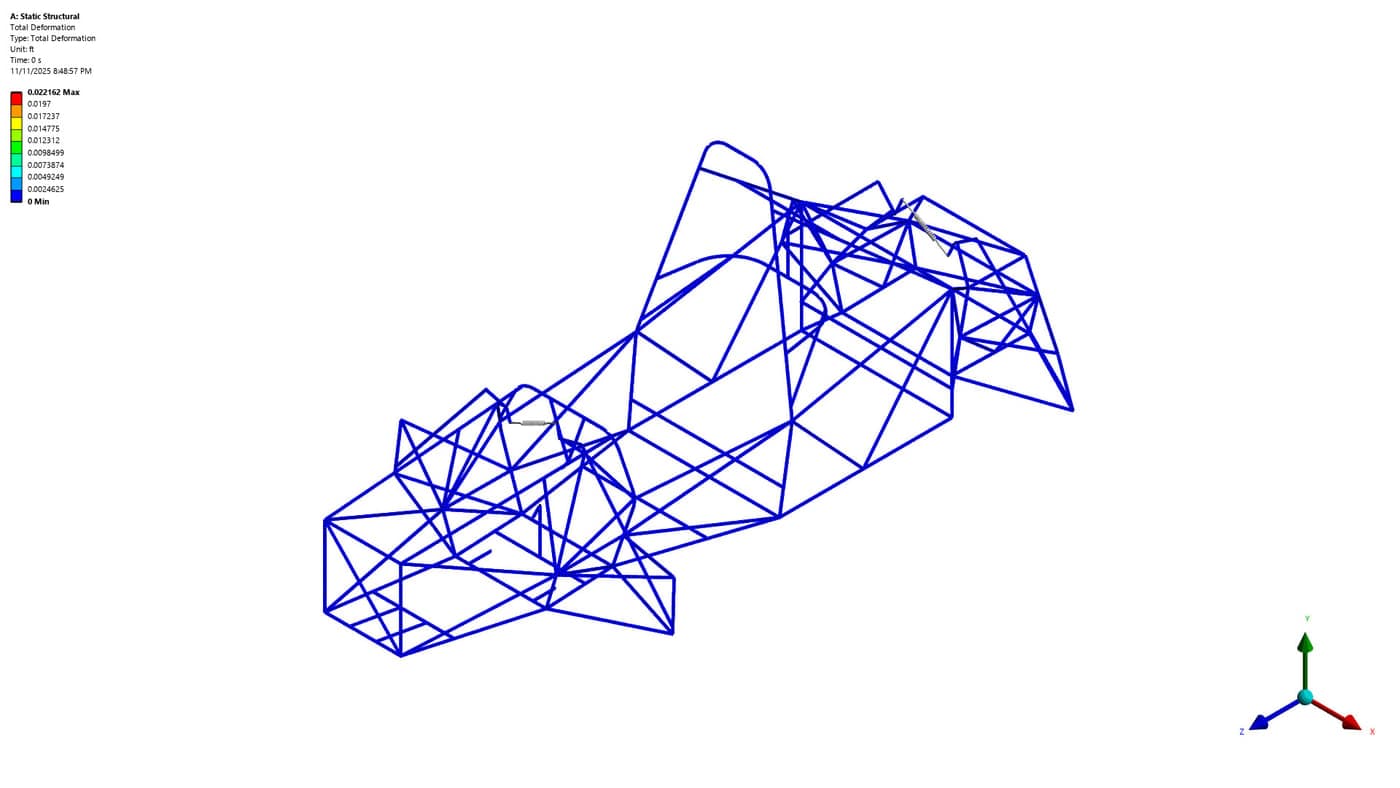
Wireframe FEA model of the Gaucho Racing formula chassis tube frame

Why Torsional Stiffness?

When a car accelerates through a turn, the lateral acceleration causes an increase in normal force on the outside tires and a decrease of the same amount on the inside tires. For a vehicle chassis, especially for racing, the suspension roll stiffnesses front and rear have direct impacts on handling through a corner — and for that to hold, the chassis itself needs to be torsionally stiff.

Consider a vehicle tube frame as a spring in series with the front and rear suspension springs.
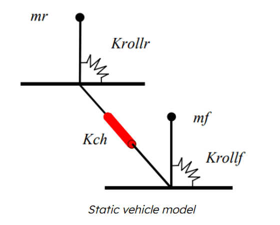
Static vehicle model: the chassis spring Kch drawn in series between the front and rear roll springs Krollf and Krollr.
The chassis (Kch) sits in series with the roll springs.
1keq=1Kch+1Krollr+1Krollf
Springs in series.

Given that F = k_eq × x, a stiff chassis would produce different resultant forces compared to a softer one. For a soft chassis, the frame twists when the vehicle is cornering. That gives a difference in compression between the front and rear roll springs, making them less effective to tune. For an ideal stiff chassis the spring travel would be equal, so lateral load transfer depends on roll stiffness alone. So I aimed to test, validate, and iterate our FSAE tube frame to be stiff enough to transmit the torques.
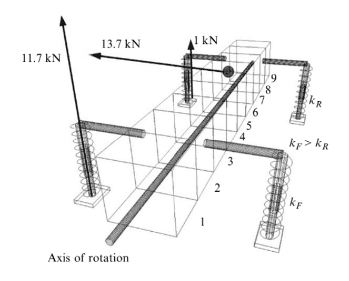
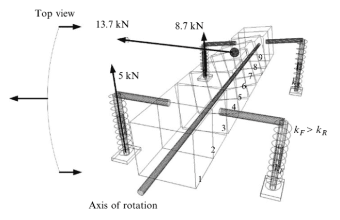
Load transfer diagram for a stiff frame: 13.7 kN input resolving to 11.7 kN at the front roll spring and 1 kN at the rear.
Stiff frame — 11.7 kN front, 1 kN rear.
Top view of the same load case with the frame twisting: the 13.7 kN input now splits 8.7 kN front and 5 kN rear.
Soft frame: 5 kN front, 8.7 kN rear. Showcases the undesirable effects of a twisting chassis.

Approach

First, I ran a number of static FEA simulations analysing the chassis with a torque load applied to the front uprights. By constraining the rear of the vehicle and allowing rotation around a fulcrum at the front, I could simulate the load paths of a cornering vehicle.
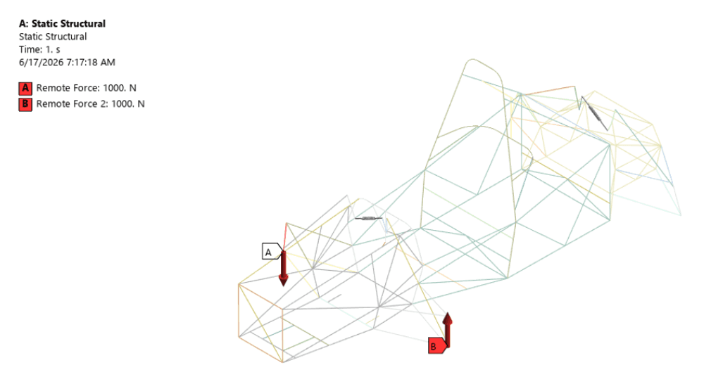
ANSYS static structural model of the tube frame with two 1000 N remote forces applied at the front uprights and the rear constrained.
ANSYS static structural — 1000 N remote forces at the front uprights.

Then I managed the design and manufacturing of a test fixture to experimentally validate those simulations and bring them closer to accurate numbers.

Process
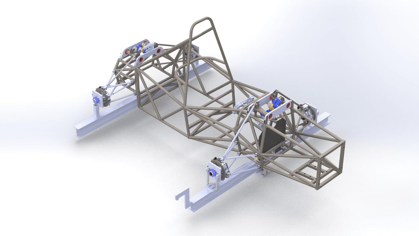
CAD render of the formula chassis mounted in the torsion test fixture, supported on blue rails at each corner.
The chassis mounted in the test fixture by all four spindles.
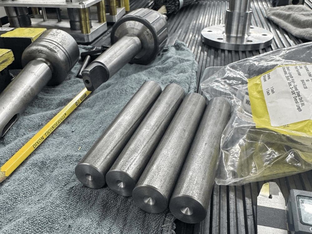
Lengths of steel round bar and tube laid out on a workbench alongside a tape measure.
Stock for the fixture.
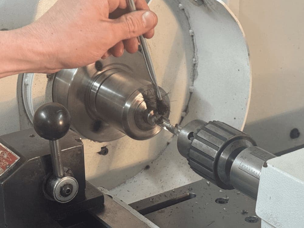
Turning a mounting shaft on the lathe, working the tailstock by hand.
Drilling and tapping the fixture pushrods.
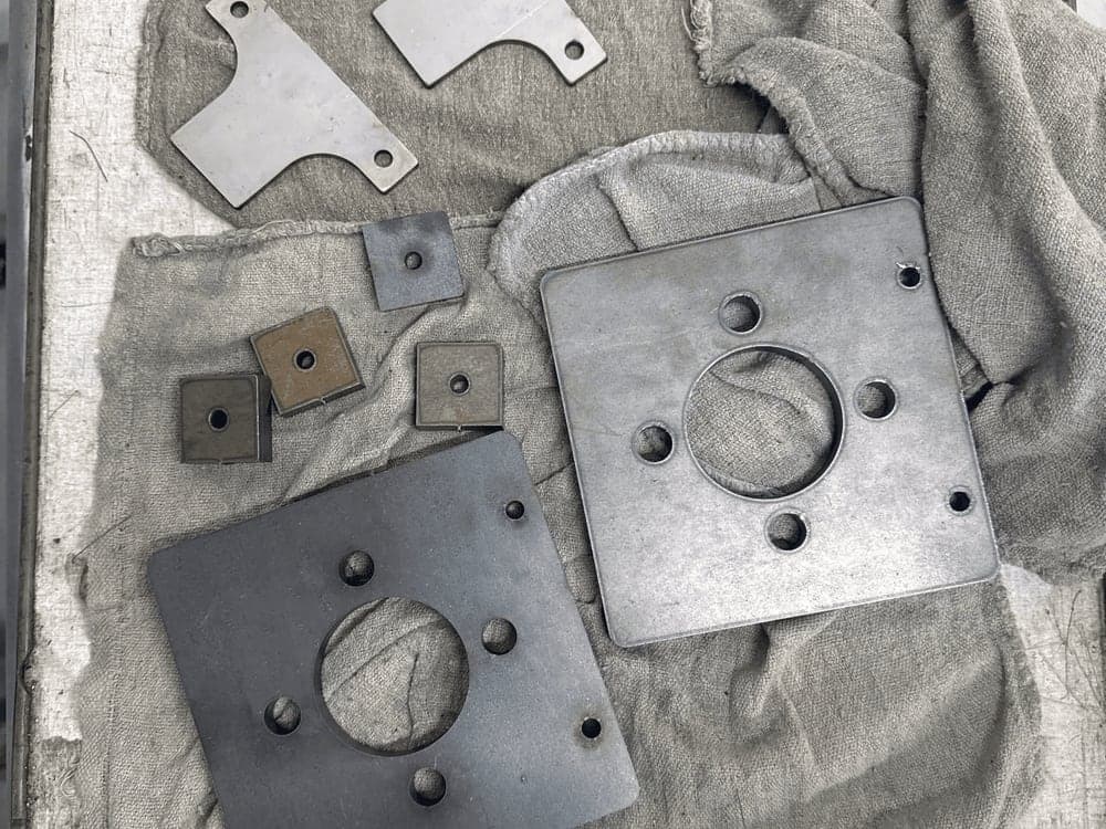
Cut steel plates and brackets laid out on a cloth before welding.
Cut plates and brackets.
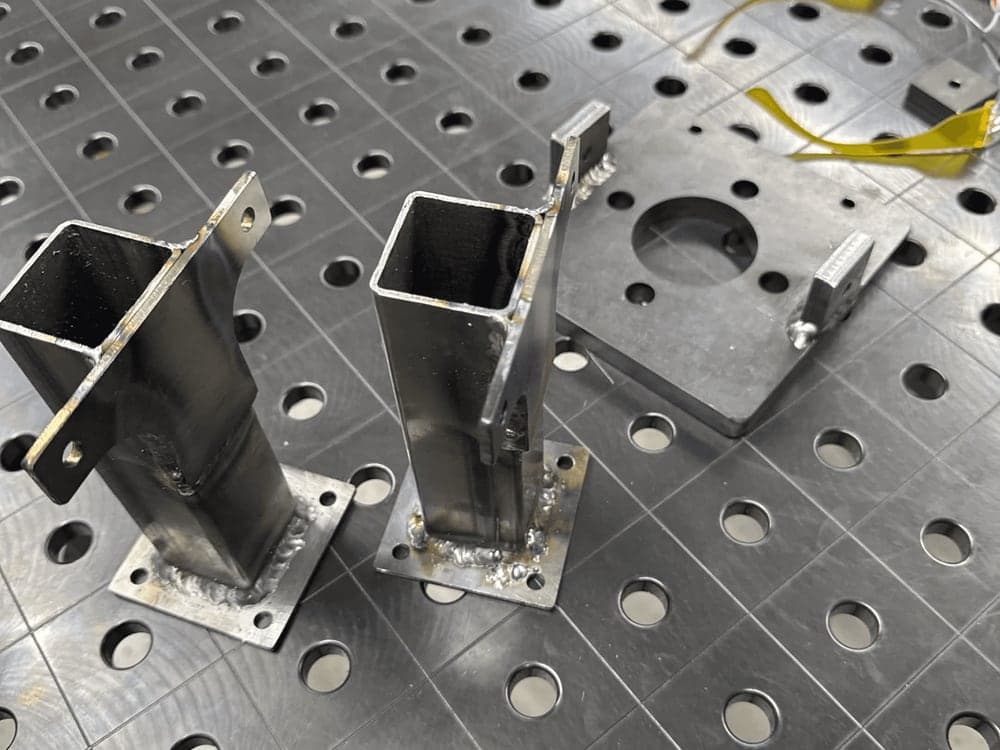
Welded square-tube uprights clamped on a fixture table.
Rear mounting uprights and a spindle plate welded together.

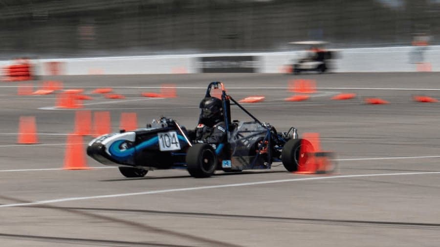
Images for the test fixture are pending due to the FSAE EV Competition in Michigan. Here are some photos from the event, and of the chassis.
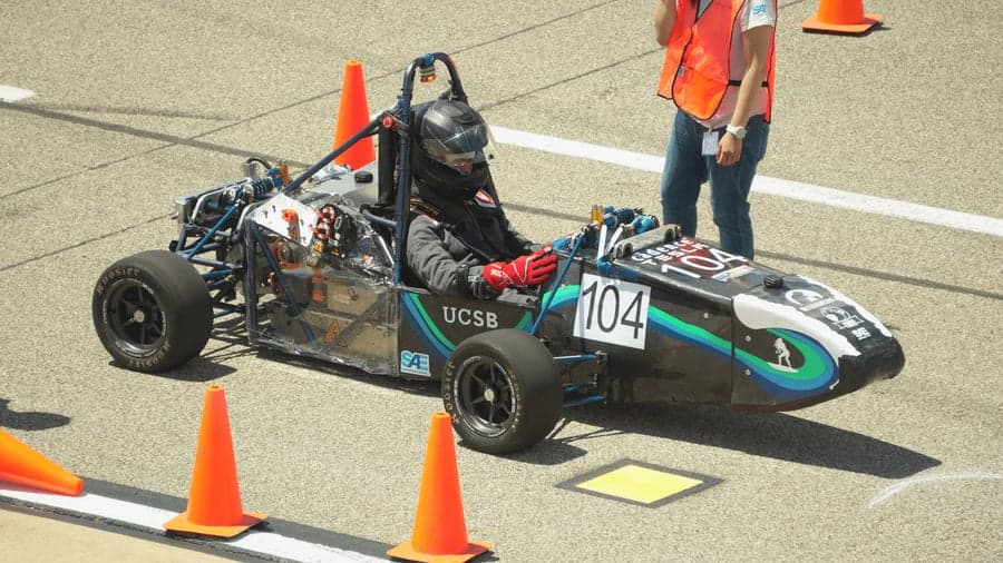
The UCSB car, number 104, staged between cones at the start of a run with the driver seated.
On the line at Michigan.
The car cornering through a cone course during a dynamic event, panned with motion blur.
Running a dynamic event.
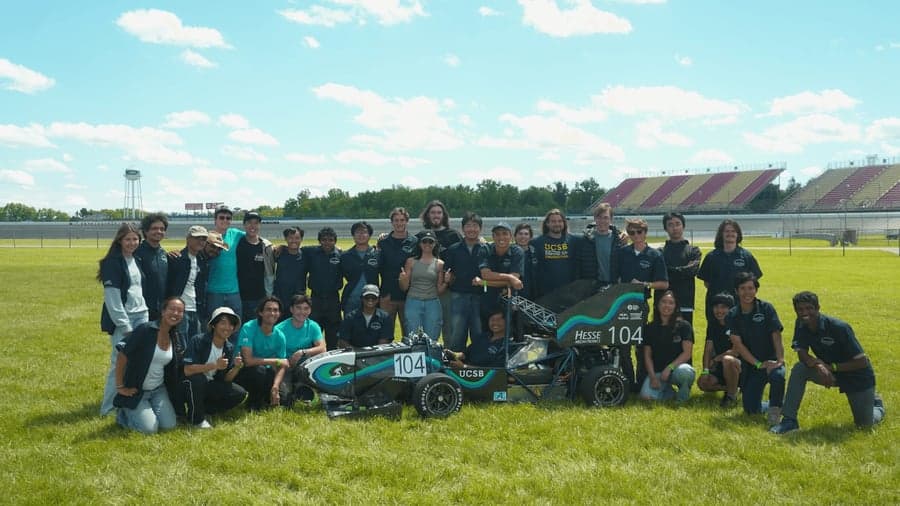
The Gaucho Racing team gathered around the car for a group photo on the grass at competition.
The team with the car.

The results of this test will assist chassis design in future years as I improve the simulation accuracy — especially useful as I move on to be Gaucho Racing’s Chassis Lead for ’26–’27.

Contact

Let's build
something.

Open to internships, research collaborations, and interesting projects. If you're working on something ambitious, I'd love to hear about it.

Jeremy Sevilla© 2025 · jeremysevilla@ucsb.edu