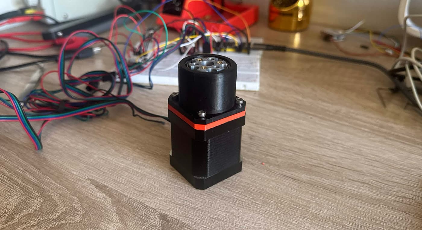
The problem
Like a lot of the robotics projects nowadays, I wanted to build a robotic arm on a budget. I had a number of NEMA 17 stepper motors I had laying around, but they only had a holding torque of ~0.39 Nm. So, to increase the torque output I decided to build a gearbox that was inexpensive, repeatable, and as efficient as possible.
Approach
I designed the gearbox as a systematic process — define the constraints, prototype, test, and iterate.
Requirements
A compact cycloidal gearbox that is lightweight, inexpensive, and efficient.
- 5 DOF robotic arm with a max torque at the shoulder of at least 0.840 kg (2 NEMA 17 stepper motors)
- Gear ratio of at least 15:1, with an efficiency of η > 60%
- Allowable backlash of ~1°
- Mostly 3D printed
Design
The major components I settled on for the gearbox:
- Two cycloidal rings
- Compared to one ring, having two (mostly) counteracts the moment incurred around the motor shaft, reducing vibrations caused by the moving gear.
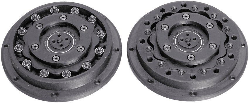
- Non-pinwheel
- Typical cycloidal gears use metal shafts and bearings for the outer lobes. A non-pinwheel design reduces manufacturing cost and assembly time, and minimizes components.
- Dimensions
- To stay compact, the whole gearbox had to sit within the NEMA 17 motor faceplate, 42.3 mm × 42.3 mm.
Process
After a number of iterations, the current set of 3D printed components was driven by both packaging constraints and torque goals.
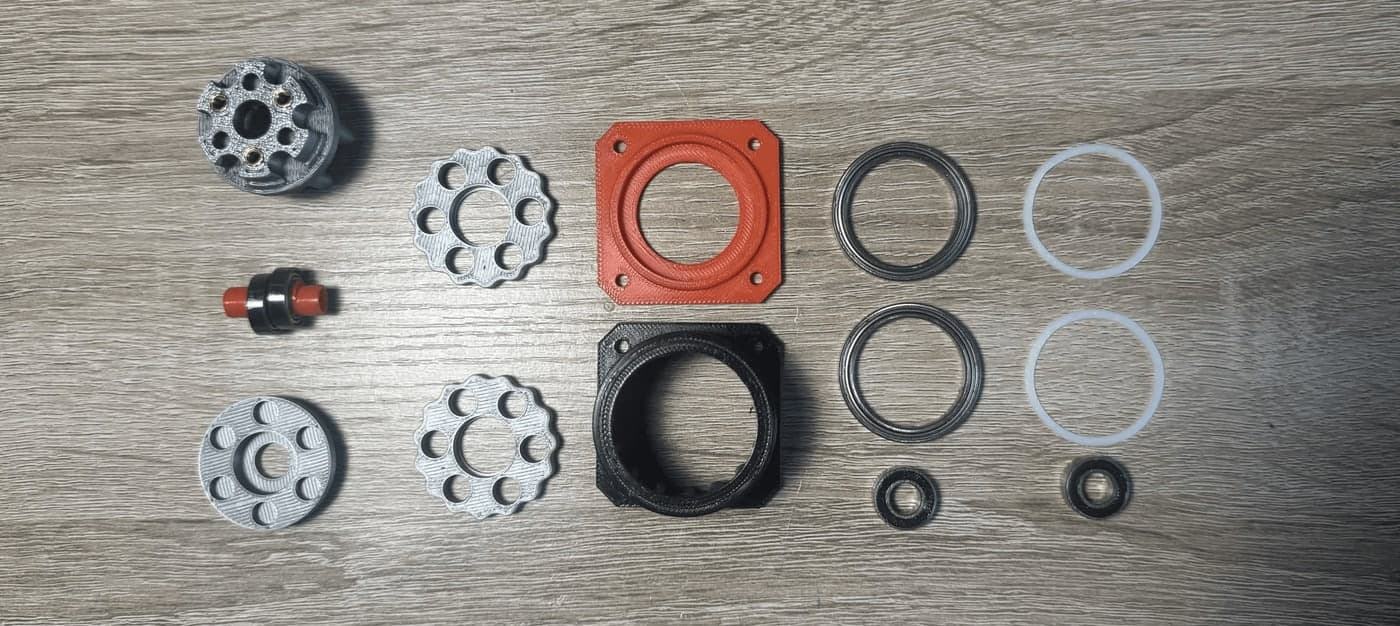
- Output shaft and end cap
- The output shaft in the top left of Figure 2 converts the gearbox's speed reduction into output torque for the arm. Since it is 3D printed, I added an end cap to omit the cantilevered nature that some other cycloidal designs have.
- Eccentric shaft
- Drives the cycloidal action with its two offset lobes. The inner diameter of the central two lobes is larger so the cycloidal rings and their bearings can be assembled onto the shaft in one piece.
- PTFE washers
- I often found the cycloidal rings would not stay perfectly parallel without a washer constraining their motion. PTFE is lightweight, thin, and low-friction, so it constrains the gears with minimal effect.
- Gearbox casing and closeout
- The casing (black) and its closeout (orange) hold the assembly together and carry the lobes the cycloidal rings are driven against — the non-pinwheel design I opted for.
Testing
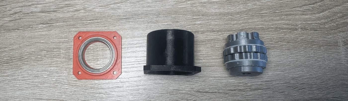
In testing, Version 1 of the gearbox performed terribly. It was loud, lacked any bearings, and had an efficiency of 37%. But it was a start.
For Versions 2 and 3 I improved the design by minimizing unwanted motion and friction, and improved the test setup alongside it. Using a load cell and code to ramp the lever arm — rather than slamming it — gave a more accurate reading with closed-loop feedback. That brought efficiency up to 70%.
Still a start, and I am still making improvements (contact FEA), so check back as I update this page with the latest design.